The steps illustrated above are set out in the following table, which includes some exapmples of Architecture Views that can be used to capture these steps in artifacts that communicate an architecture to relevant and respective stakeholders. Views are not constrained for use by the quoted examples. Enterprise Architecture will develop and evolve for particular circumstances and should from an architecture library for use as appropriate with whatever naming conventions and descriptions achieve the objectives of clearly describing an archiecture and informing those wioth an interest in it.
| Business Architecture | |
|
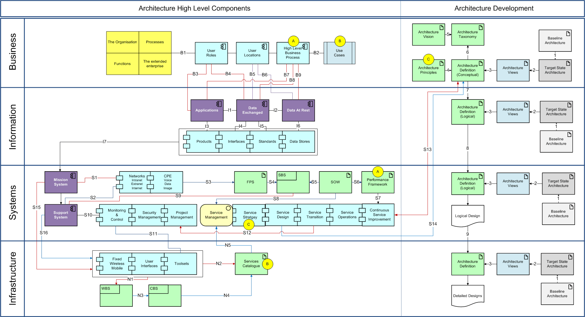
Business Architecture is necessary as a means of demonstrating:
| |
| B1 | Business Architecture primary components. An organisation's Business Level architecture is captured in terms of the relevant users'
(or actors') roles, the locations those roles are conducted from and the business processes that those roles fulfil. Architecture View: SerV-R Service Requirement Definition |
| B2 | Use Cases to business processes. Can be used to describe the business processes. Use Cases are a representation of steps, typically defining interactions between a role and a system, to achieve a goal. The user / actor can be human or an external system. Use cases provide guidance for design work, validate designs and provide inputs to the Services Catalogue. A Use Case could set out the end-points in an interaction and the transit steps between the interactions. |
| B3 | User roles to Applications. Will identify the applications necessary to perform a function. An application can be software or a technology (e.g. email, telephone, collaboration session, video link etc). User roles determine access privileges. |
| B4 | User roles to Data Exchanged. A user may be human or a machine. The nature of the data exchanged to fulfil business functions. |
| B5 | User locations (which may not be fixed) to Data Exchanged. Sets the geographic footprint for the reach of a network to facilitate data access and data exchange. |
| B6 | User locations to Data At Rest. Describes the locations of stored data and sets boundaries for accessing centralised or distributed data stores. |
| B7 | Business processes to Applications. Business processes shape the applications required for their completion. An application may be software or a technology. Identifies priorities (e.g. business-critical applications) and service measurables (e.g. Class Of Service, Quality Of Service). |
| B8 | Business processes to Data Exchanged. B2B, B2C and internal exchange of data to facilitate the business processes. |
| B9 | Business processes to Data At Rest. Data storage and access to facilitate business processes. Identifies requirements for data protection (security, availability, and replication) and accessibility. |
| Information Architecture | |
| I1 | Applications to Data Exchanged. Applications shared between end points. Systems types, dimensions and configurations between end points. Architecture View: Component Diagram |
| I2 | Data Exchanged to Data At Rest. Accessibility and access rights for stored data. |
| I3 | Applications to products. Product is a generic term, applicable to COTS and custom software. Application may be software or type of technology (e.g. video). A more detailed description of information. |
| I4 | Data Exchanged to interfaces. Non-technical description of the end points and the interfaces between them to provide for the
identification of component systems e.g. - smart-phone / 3G-4G / PSTN / WAN / firewall / server. Architecture View: SerV-6 Service Resource Flow Matrix, SV-3a System-System Map. |
| I5 | Data Exchanged to standards. Technical standards (e.g. TCP IP, MPLS, 802.11 etc.), QOS / COS requirements, firewall rules and security policies and any other such standard applicable to the context. Architecture View: OV-2: Operational Information Exchange. |
| I6 | Data At Rest to data stores. Data At Rest / Data In Use, and centralised, distributed or end-point data archiving derived from Baseline and Target (possibly also Future state) accessibility and protection boundaries based on the business function requirements. |
| I7 | Data to Mission System. Data required by a Mission System to fulfil its functions. |
| Systems Architecture | |
| S1 | Mission System. A description of the component networks and Customer Premise Equipment (CPE) systems that make up a Mission System and how those systems support the mission (i.e. business function). The boundaries between network and CPE are subject to an architect's interpretation. PaaS could be considered either network or CPE, a provider's equipment housed at a client site could also. Consistency is usage is the important factor. Consider an ontology - in computer science and information science, an ontology formally represents knowledge as a set of concepts within a domain, and the relationships between pairs of concepts. It can be used to model a domain and support reasoning about entities. Architecture View: SerV-4 Service Functions, NetV-1 Conceptual Network Model |
| S2 | Support System to networks and CPE. Serving the same purpose as describing Mission Systems - however Support Systems should be developed from the Mission System. |
| S3 | Functional Performance Specifications. Defines the functional requirements for the item, the environment in which it must operate and the interface and inter-changeability characteristics. |
| S4 | System Breakdown Structure. A taxonomy of a system setting out its component parts. |
| S5 | Statement Of Work. Documentation of the work activities, deliverables and timelines that define the scope for a particular piece of work - as a project or as operational scope. Establishes the boundaries for architecture. |
| S6 | Performance Framework. The standards and metrics applied to measure the success of a service and / or technology framed in a way that identifies key measures that map to business priorities and that, ideally, is structured in a way that encourages overachievement and innovation. Service level agreements are a subset of a Performance Framework, setting out the metrics to apply. |
| S7 | Performance Framework to Continual Service Improvement. A Performance Framework and its constituent service levels should provide a means to measure ongoing performance, address areas of under achievement and drive for measureable, ongoing improvements. |
| S8 | Statement Of Work to Service Management. Sets out the boundaries and deliverables of the Service Management activities required to support a network. ITIL forms a comprehensive template for a Service Management SOW. Architecture View: StV-7 Capability to Service Map |
| S9 | Systems Breakdown Structure to Support System. A Mission System SBS provides inputs into the development of appropriate Support System(s). |
| S10 | Support System to Cross Functional Services. Support Systems provide inputs into the service management functions required to drive the support systems. Conversely, service management requirements will provide inputs to Support Systems required to fulfil those functions. |
| S11 | Monitoring & Control to toolsets. Network management and performance management requirements as criteria for identifying / developing the toolsets (which form a Support System or component thereof). |
| S12 | Service Transition to Project Management. Implementation of an architecture undertaken in accordance with Project Management practice.
In some circumstance architecture may be a part of a wider project, in which case the architecture work is undertaken in accordance with the project requirements as a Request For Architecture Work. Architecture View: StV-3 Capability Phasing. |
| S13 | Continual Service Improvement to Architecture Definition. Improvement initiatives identified that require architecture qualification OR variations and therefore design work. |
| S14 | Service Design to Architecture Definition. Variations to an architecture initiated through change management (Request For Change). |
| S15 | Mission System to Infrastructure Architecture. Systems descriptions sufficient to enable complete, detailed design of an architecture that meets the Target state. |
| S16 | Support System to Infrastructure Architecture. Systems descriptions sufficient to enable complete, detailed design of a Support System architecture. |
| Infrastructure Architecture | |
| N1 | Infrastructure Architecture to Work Breakdown Structure. A taxonomy of work required to implement (and possibly support) an architecture based on the components of the system. Architecture View: NetV-3 Physical Network Model |
| N2 | Infrastructure to Services Catalogue. The systems that make up an Infrastructure contribute to the contents of a Services Catalogue. Other inputs will be formed from service management deliverables. |
| N3 | Work Breakdown Structure to Cost Breakdown Structure. Activities required to implement architecture provides for the identification of the costs to do so. |
| N4 | Cost Breakdown Structure to Services Catalogue. Cost breakdown provides for pricing of the relevant components of a Services Catalogue. |
| N5 | Services Catalogue to Service Management. Service management activities that can be requested through the Services Catalogue. |
| Other links | |
| A | Business Processes to Performance Framework. The service levels applied should reflect the relative importance to the business. |
| B | Use Cases to Services Catalogue. Use Cases provide an input into the Services Catalogue, i.e. those support activities required to support a user's use of the network. |
| C | Architecture Principles to Service Strategy. Architecture Principles and Service Strategy should complement each other and support the same business outcomes. Architecture View: StV-1 Strategic Vision |
| 1 | The Baseline Architecture is the 'as-is' environment - the starting point for design efforts. Baseline Business Architecture is identified to the extent:
|
| 2 | The target state architecture (the to-be environment) portrays the future or end-state enterprise, generally captured in the
organisation's strategic thinking and plans. It is commonly referred to as the 'to-be' architecture. The target architecture is defined to the extent:
|
| 3 | An Architecture Definition Document (ADD) is a deliverable container for the core architectural artifacts created during a project. The ADD spans all architecture domains (business, information (data, application) and technology (system & infrastructure)) and also examines all relevant states of the architecture (baseline, interim and target). The views created as a result of the architecture development process provide visual and/or textual renderings of the underlying architectural data and convey information of interest from the Architectural Description needed by specific user communities or decision makers. Architecture View: StV-2 Capability Taxonomy, SerV-3a Service-Service Map |
| 4 | Architecture Principles are the set of rules to guide business, information and technology decisions. They apply to the initial solution design, and across the lifecycle of any Service, and its components, through incorporation into change procedures. Architecture Principles should apply uniformly across an ICT environment, to guide and align all architecture efforts. |
| 5 | Architecture Vision to Architecture Taxonomy. A vision for an architecture will shape the way a network structure is set out. Architecture View: AVS Architecture Vision |
| 6 | Architecture Definition to Architecture Taxonomy. The taxonomy is a subset of an architecture Definition - setting out the hierarchy and interdependencies of the components of an architecture. Architecture View: ADD Architecture Definition |
| 7 | Business Architecture to Information Architecture. The Business Architecture informs the Information Architecture by describing the information requirements to fulfil business processes and functions and where these are undertaken (what, why, how, who, where and when as is set out in both Zachman and SABSA). |
| 8 | Information Architecture to Systems Architecture. The Information Architecture informs the Systems Architecture by describing how information / data / applications is used by an enterprise. |
| 9 | Systems Architecture to Infrastructure Architecture. The descriptive, logical level of the Systems Architecture is developed in detail (physical) at the Infrastructure level. |